

Marcus Vance
Lead Systems Architect •
A technical investigation into modular subassemblies, standardized fastener matrices, and configuration management across three concurrent product tiers.
Part Commonality Index
Tooling Capital Expense
Consolidated Fasteners
Annual Inventory Savings
Balancing geometric differentiation with structural component reuse.
In multi-tier product families, designing around shared internal architecture significantly reduces development cycles and manufacturing complexity. By establishing frozen core geometries—such as unified motor mounts, standard bracket extrusions, and shared bus interfaces—engineering teams can release distinct customer-facing variations without duplicating high-cost tooling. The CAD framework relies on a skeleton master model where primary locating datum planes govern all downstream variant configurations.
During the cross-tier analysis of the mechanical actuator series, consolidating the internal drive chassis across standard, compact, and reinforced versions eliminated four redundant casting molds. The outer chassis accommodates varied external duty cycles through modular faceplates and configurable seals, while 64% of the internal Bill of Materials remains entirely identical across all production variants.
Master CAD Driver
Single Top-Down Skeleton
Subassembly Reuse
7 Shared Core Modules
BOM Consolidation
82 Unique to 29 Common
Lifecycle Impact
22% Faster ECO Turnaround
Implementing extensive part sharing introduces subtle constraints in peak weight optimization for entry-level models. Over-engineering a standard structural rib to withstand loads expected in premium variants slightly increases mass for lower-tier units, yet the resulting economies of scale in procurement and automated assembly overwhelmingly offset material cost increments.
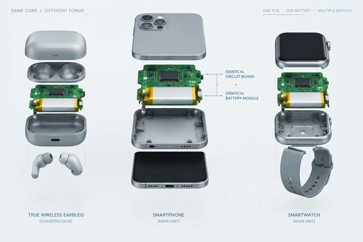
Exploded CAD hierarchy displaying shared transmission core within differentiated enclosures.
Consult our senior CAD systems architects to audit your assembly trees and unlock modular cost savings.
Join the academic discourse regarding this component analysis.
Lead Systems Architect •
Author •
We implemented kinematic constraint locating pins directly into the shared internal chassis, isolating the outer sheet metal tolerance variations from affecting core gear mesh alignments.

How did your team handle the tolerance stack-up analysis when locking in the shared mounting bracket across the cast aluminum versus stamped sheet metal enclosure variants?