
Spatial Orientations
Ingress Protection Range
Shared Core Fasteners
Parametric CAD Rework
Environmental Factors and Mechanical Adaptation
Balancing universal structural frameworks with location-specific mounting interfaces.
Industrial machinery routinely operates across vastly different physical configurations, ranging from vibration-heavy factory concrete floors to suspended overhead steel trusses and outdoor maritime bulkheads. When engineering a single equipment line to serve these contrasting contexts, architects face a fundamental choice: develop completely separate product SKUs or establish a modular configuration platform that adapts through interchangeable sub-assemblies.
Adopting a configuration-driven parametric framework allows designers to isolate sensitive operational cores—such as motor drive spindles and internal fluid pathways—inside a standardized inner envelope. External brackets, cable gland positionings, thermal dissipation fins, and vibration dampening pads then configure dynamically around this core, preventing expensive alterations to primary casting or machining tooling.
Configuration Parameters Under Study
Vibration Isolation
Elastomeric vs Rigid Flange
Thermal Dissipation
Natural Convection vs Forced Air
Ingress Sealing
O-Ring Gaskets & Labyrinth Seals
Tooling Reusability
86% Cast Core Uniformity
Critical Trade-Offs in Multi-Environment Variants
Field installations demonstrate that ignoring localized mounting mechanics leads to premature joint fatigue, thermal bottlenecks, and labor-intensive on-site custom modifications. Structural analyses highlight three primary considerations when maintaining shared CAD assemblies across variant lines:
- Dynamic resonant frequencies vary drastically between rigid floor anchorages and flexible suspended bracket systems.
- Enclosure seal degradation accelerates when thermal expansion mismatches between dissimilar bracket alloys occur under cyclic outdoor exposure.
- Cable routing and service access clearance requirements invert between wall-hung and low-clearance ceiling installations.
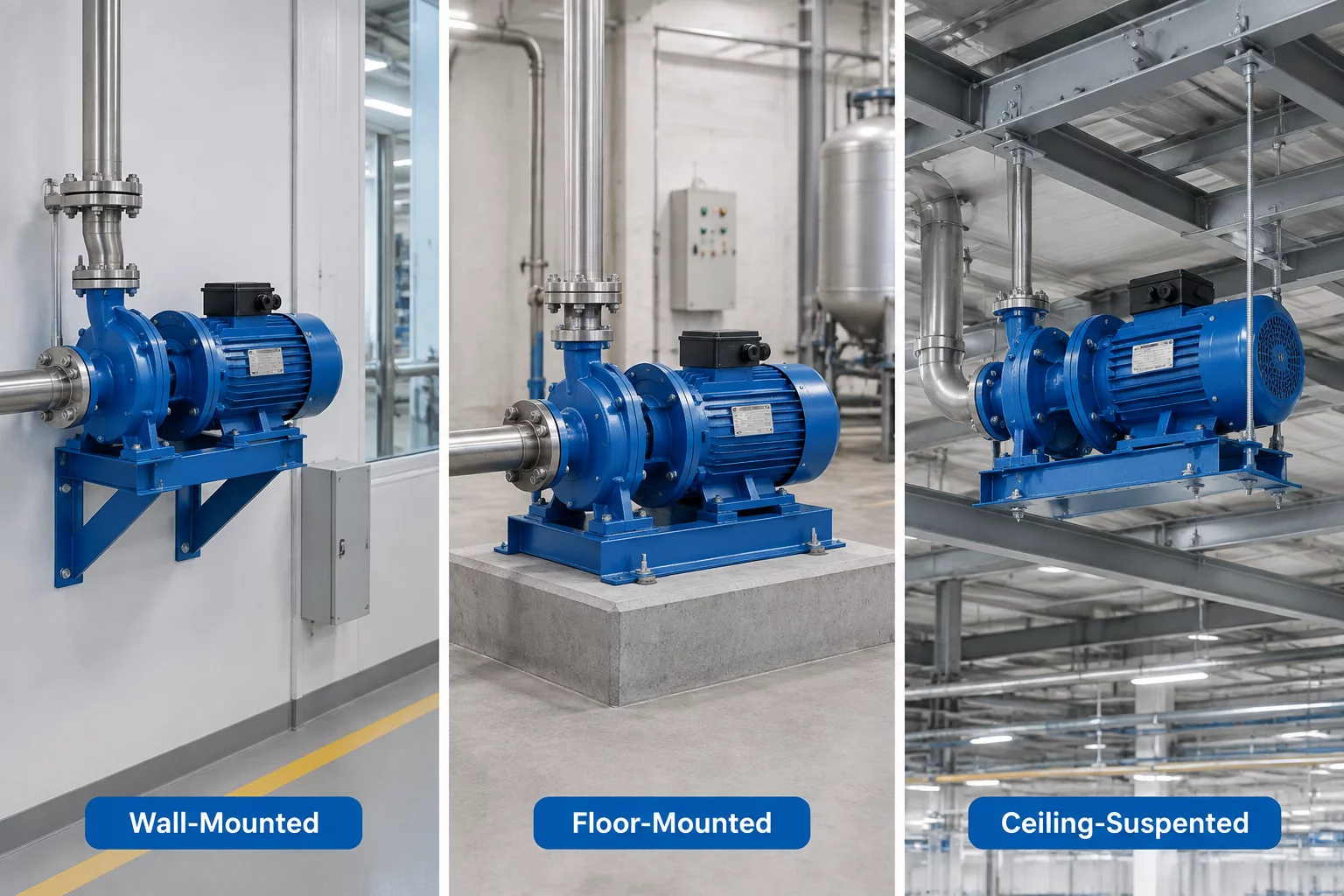
CAD configuration variations for wall-mounted, floor-anchored, and overhead suspended installations.
Variant Comparison Specs
Related Case Studies
Need Tailored Variant Modeling?
Review custom configuration trees and parametric mounting guidelines with our design engineering specialists.
Peer Discussions & Peer Reviews
Join the academic discourse regarding this component analysis.
Leave a Thoughtful Contribution