

Marcus Vance
Lead Systems Architect •
A comprehensive framework for developing scalable articulating bracket systems with standardized interface geometry, shared pivot joints, and parametric extension links.
Shared Joint Tooling
Base Configuration Matrix
Max Articulated Payload
BOM Part Consolidation
Establishing structural datum planes and rotational coupling points across multi-axis assemblies.
Designing a versatile adjustable mount family begins with isolating the primary load-bearing pivot cores from application-specific mounting flanges. In heavy-duty display and industrial equipment positioning, individual custom castings for every extension length drastically inflate manufacturing tooling costs. By standardizing the cylindrical knuckle interface and friction clutch collar across the entire product tier, engineering teams can configure short-reach single-axis brackets, dual-link articulating arms, and heavy counterbalanced desk clamps using identical internal hardware.
Dimensional scalability is driven by parametric extrusions and symmetrical cast hubs. The mounting base establishes a universal three-point bolt pattern, accommodating wall anchors, standard VESA plates, and circular pole clamps without altering the primary articulation sleeve. SOLIDWORKS configuration tables control the arm reach parameters and internal cable routing channels, allowing automated draft generation and consistent FEA stress verification across light-duty (5–15 kg) and high-load (up to 65 kg) variants.
Joint Standard
Ø32mm Knuckle Core
Material Base
A380 Cast Aluminum
Clamping Mechanism
Constant-Torque Disc Stack
Extension Range
120mm to 780mm Reach
Multi-axis adjustable mount families require balancing dynamic deflection against quick-release adjustability. Tighter tolerances at the friction disc interface eliminate unwanted backlash under maximum cantilevered extensions, but necessitate high-precision CNC finishing on cast mating faces.
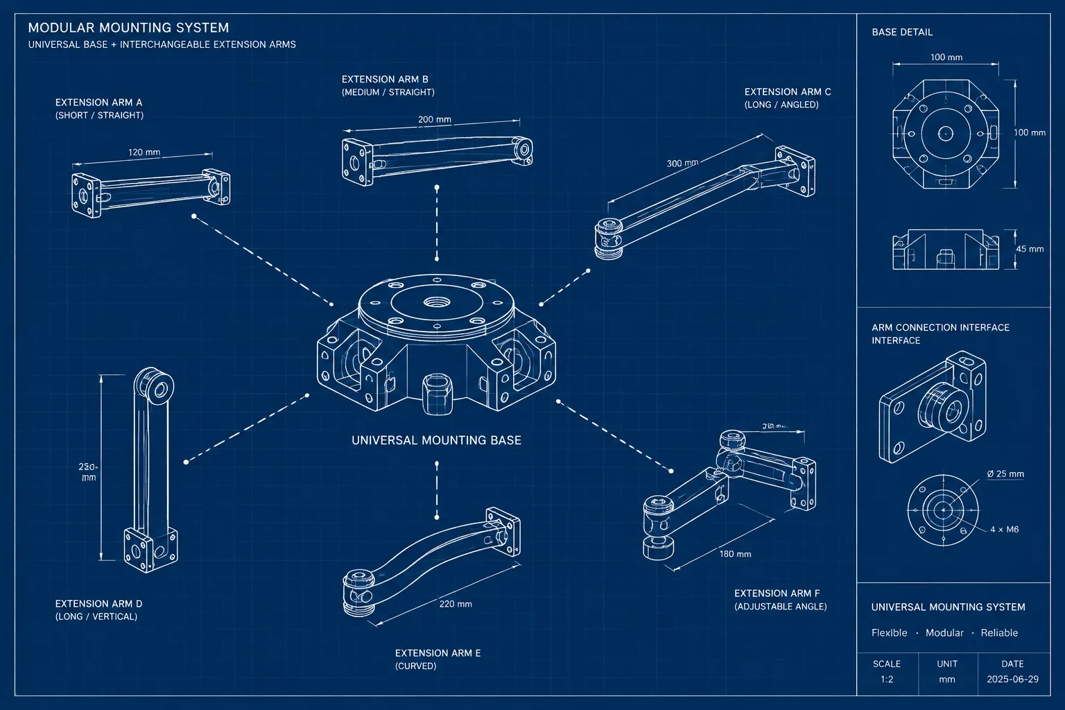
Master assembly schematic illustrating universal base coupling and modular extension link pathways.
Consult with our mechanical design specialists to organize parametric subassemblies and eliminate redundant component variants.
Join the academic discourse regarding this component analysis.
Lead Systems Architect •
Author •
Marcus, we integrated slotted Belleville spring washers into the friction stack to compensate for thermal dimensional drift between -20°C and +60°C, maintaining constant clamping torque without manual retightening.

Isolating the Ø32mm knuckle core is a smart move for maintaining uniform damping friction across the family. How are you handling thermal expansion variations when these mounts are deployed in unconditioned industrial facilities?