
Rebuild Latency Cut
Max Config Depth
Mate Integrity Rate
Average Cache Footprint
Architecture of Split Configurations
Structuring top-level models to isolate variant complexity without corrupting parent references.
When industrial CAD assemblies scale across dozens of product variants, packing every geometric permutation into a single top-level configuration tree creates catastrophic file bloat. Top-level rebuild trees become fragile when feature suppressions trigger unhandled parent-child dependency breaks. Implementing a split-configuration architecture isolates functional modules into decoupled sub-branches, where variant geometry resolves locally before propagating upstream.
Engineers achieve this separation by utilizing external envelope references and skeleton master sketches. By anchoring mounting interfaces to shared datums rather than transient solid faces, variant modules can be hot-swapped or suppressed entirely without throwing mate errors in adjacent subsystems. This modular hierarchy preserves memory bandwidth during multi-body recalculations.
Configuration Strategy Metrics
Reference Method
Skeleton Datums
Suppression Model
Sub-Tier Isolation
Data Cache
Selective Purge
Assembly Rule
Zero Circular Mates
Implementation Best Practices & Rebuild Control
Managing divided configuration paths requires strict governance over feature tree states and suppressed component references. When downstream drawing views or BOM tables evaluate complex models, unorganized split setups often trigger phantom rebuild cascades across unreferenced configurations. Enforcing explicit branch isolation guarantees predictable system behavior:
- Lock configuration properties to suppress newly added components automatically in peer configurations, avoiding unmanaged interferences.
- Decouple heavy cosmetic detailing and internal routing into specialized evaluation configurations rather than primary modeling states.
- Standardize naming syntax across split branches to maintain synchronized design table links and automated BOM rollups.
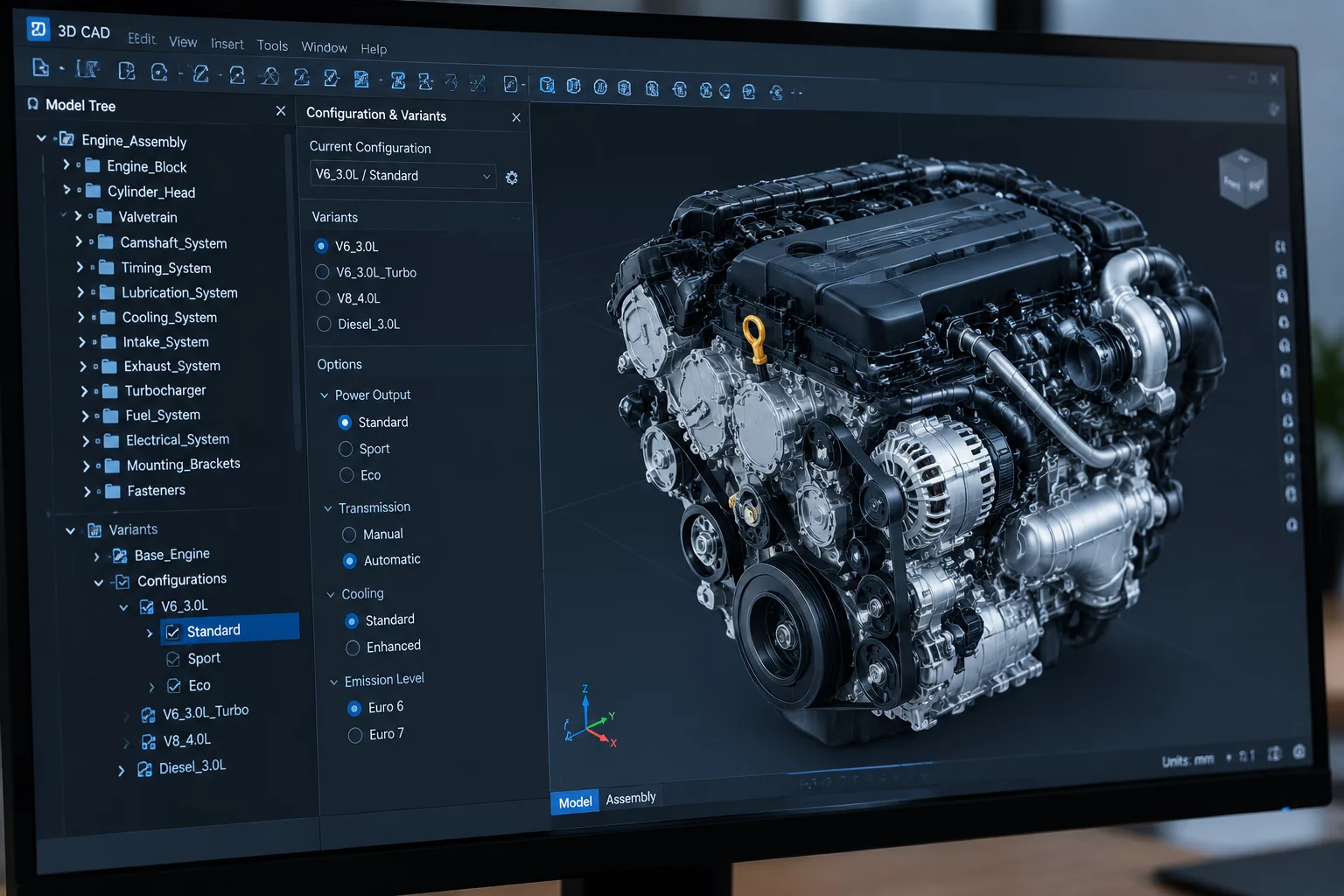
Figure 4.1: Parametric branch isolation tree demonstrating sub-tier suppression boundaries.
Configuration Parameters
Related Engineering Guides
Need CAD Variant Optimization?
Consult with our engineering team to audit your complex configuration trees and streamline multi-model workflows.
Request Engineering Consultation
Submit your CAD modeling requirements for specialized configuration tree optimization.
Peer Discussions & Engineering Insights
Join the technical discourse regarding this CAD configuration study.
Leave a Thoughtful Contribution